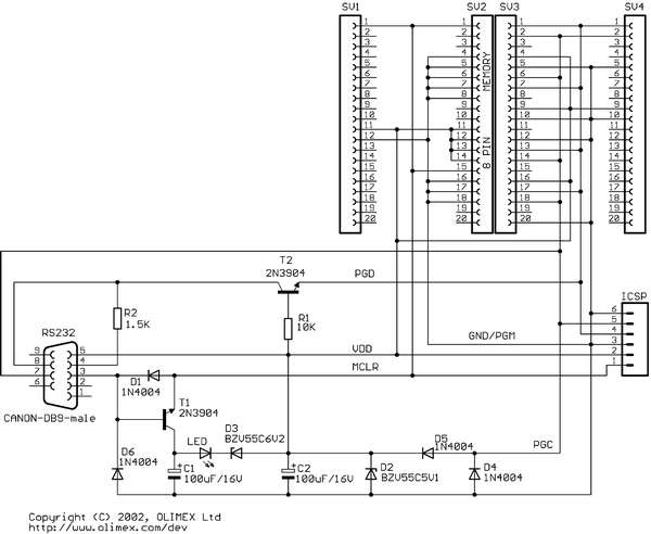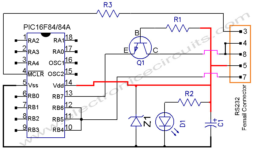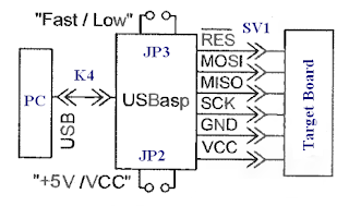

PS/2 Keyboard, standared chip for user, PIC16F877A is the default chip of PIC Ultra 2+, It has 8K bytes of linear program, / Schematics 2) Software / Example PCB color : RED / Purple MCU : 1) PIC16F877A (on-Board) x1 2 USB-UART communication module / Arduino programmer 5.

External debugger (ICD3) connector / PICKit2/3 4. 19 Modules Programming On-board programmer.
USB PIC PROGRAMMER CIRCUIT DIAGRAM CODE
It is based on the Microchip PIC16F877A single-chip FlashĬom/files/mm51c/loader/WinLoad MCP100 PIC16C58 PIC16F877A RS-232 PIC16F877A pin PIC16F877A Microcontroller PIC16F877A SPECIFICATIONS PIC16F877A PIN diagram PIC16F877A block diagram PWM using PIC16F877a c code PWM Inverter using PIC Microcontroller control dc motor speed using Pic16F877A PIC16F877A circuit diagram PIC16F877A connect to 16 pin LCDĪbstract: arduino uno ASM117 28BYJ-48 ASM117-3 28BYJ48 mg995 Devices ADX元xx accelerometer PIC16f877a example code spi 24c16 wp When PIC16F877A fails to communicate with, expandable micro-controller system. If this function is activated, the PIC16F877A should communicate with PIC16C58 through the I2C bus to prevent restart. Timeout is selectable from 1 to 127 seconds. PIC16C58 In-System programmer supports Software Watch-Dog timer.Hardware Watchdog timer of PIC16F877A provides protection against software failures and lock-ups.Text: -layer Printed Circuit Board, no vias.

PIC16F877a Programmer circuit diagram Datasheets Context Search Catalog DatasheetĪbstract: PIC16F877A Microcontroller PIC16F877A SPECIFICATIONS PIC16F877A PIN diagram PIC16F877A block diagram PWM using PIC16F877a c code PWM Inverter using PIC Microcontroller control dc motor speed using Pic16F877A PIC16F877A circuit diagram PIC16F877A connect to 16 pin LCD


 0 kommentar(er)
